You have no items in your shopping cart.
- SALE
- Tension Calculator
- Webbing Stretch
- Contact Us
- Free Shipping on U.S. Orders $89+

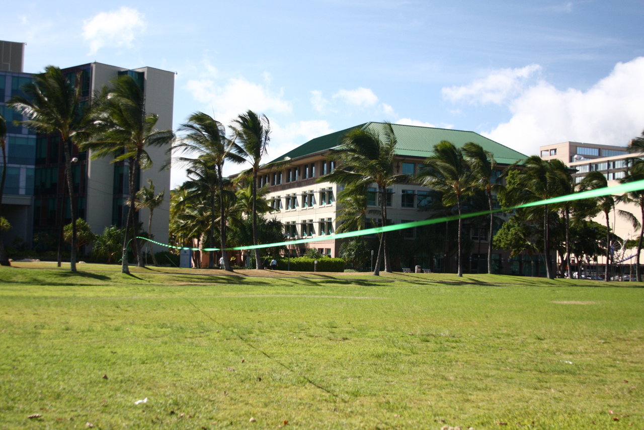
A test comparing the cyclic loading of a longline with and without wind dampeners on a windy day. Article written by Sayar Kuchenski.
Introduction
Anyone who has longlined in high winds knows that the wind can cause subject serious vibrations and sinusoidal oscillations to the line, especially without wind dampeners. Although the oscillations generated without wind dampeners can appear to wreak devastating loads on a longline, very little research exists about how much force the wind can subject.
Methods
The method in which I recorded the oscillation phenomenon is quite simple. I rigged two 250’ longlines, one lightweight polyester and one super low-stretch high-tech webbing, with a dyno scanning at 300 Hz. in line with the anchor, and I recorded the load readings for a 5-minute sample, both with and without wind dampeners. I then combed the data and I will show you the highest recorded load for each sample pool. While the samples were not subjected to a whole gale, NOAA reported winds in the area averaging 14 MPH with 33 MPH gusts, so the lines were subjected to continuous, moderately strong wind for the entire duration of the test. I recorded three samples: one high-tension high-tech line, one moderate-tension high-tech line and one high-tension polyester line, all at 250’. I did not stand on the line during any period in the five-minute test window.
Observations
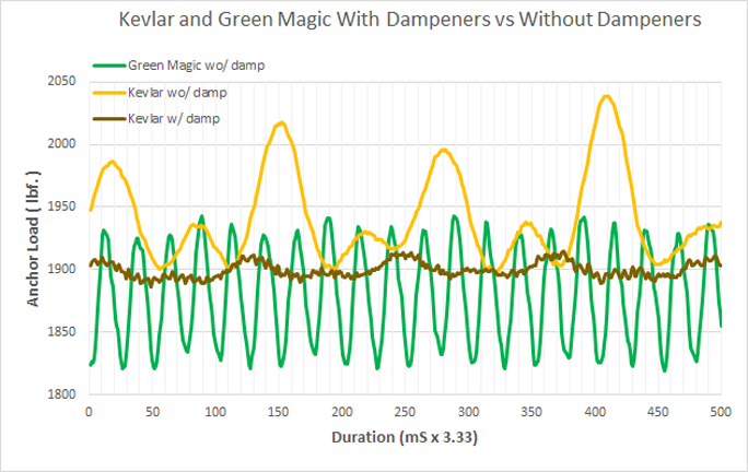
High-Tech (high tension):
- Pre-test resting tension: Approximately 1890 lbf
- Peak load without dampeners: 2039 lbf. (+149 lbf)
- Load cycles per second (mean): 2.75
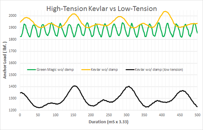
High-Tech (moderate tension):
- Pre-test resting tension: Approximately 1217 lbf
- Peak load without dampeners: 1407 lbf. (+190 lbf)
- Load cycles per second (mean): 2.75
Lightweight Polyester
- Pre-test resting tension: Approximately 1860 lbf
- Peak load without dampeners: 1942 lbf. (+82 lbf)
- Load cycles per second (mean): 13
- Peak-to-peak load (maximum): 115 lbf
High-Tech (high tension) with wind dampeners:
- Pre-test resting tension: Approximately 1890 lbf
- Peak load without dampeners: 1915 lbf. (+25 lbf)
Conclusions
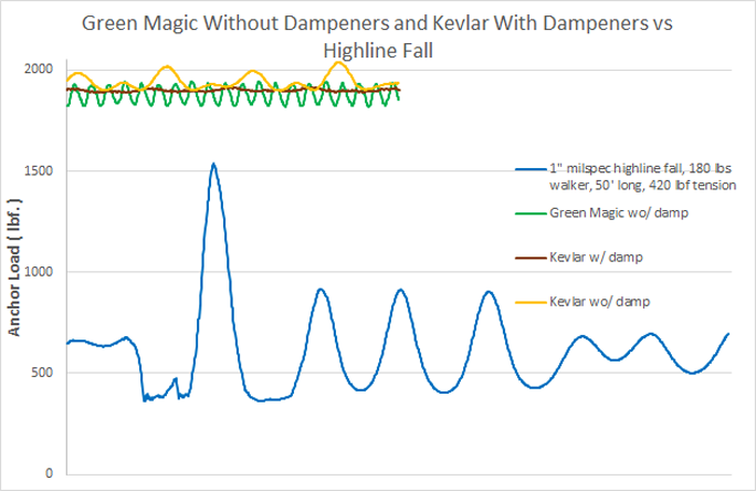
Although it may appear that the wind was subjecting the line to extreme loads, the load increase caused by the wind was actually quite small. In fact, standing in the middle of the line subjected the line to more force than the wind did. This can be explained easily by examining the amount of sag the wind subjects to the line. While the wind was causing peak-to-peak oscillations of over 4’, the downward sag subject to the line was only around 2’. When I stood on the line I subjected nearly double that. The following graph shows how the load fluctuations are relatively small compared to known high-loading events such as a highline fall.
However, there are some very legitimate concerns regarding the vibration and cyclic loading presented to the pulley system and anchor components when the line is allowed to flop in the wind. The extreme vibration, as seen in the video, caused every screwgate steel carabiner in the system to unlock within a matter of seconds. In addition, if allowed to propagate and continue for an extended period, the vibration will cause severe wear to any aluminum-to-steel contact point, such as the contact point between a shackle and aluminum rigging plate. Last, the alarmingly high number of cyclic loads (13 per second for Green Magic), brings into question the long-term fatigue suitability of the tensioning system, especially aluminum components.
According to Hairer (2012), at least one type of large AL-7075 aluminum carabiner will fail at 240,000 cycles if subjected to 225 lbf load cycles with a mean tension of 1,350 lbf. With an increase to 1,800 lbf of tension and a load-cycle range of 450 lbf, a large carabiner can fail with less than 35,000 cycles. At a rate of 13 cycle per second, the anchor would see 35,000 cycles in just under 45 minutes.
Considering the cyclic-loading nature of a longline in the wind, it would be most advantageous to use wind dampeners under all conditions, and if a longliner were to leave a line up for an extended period, she or he would be well off to softpoint the system and remove any aluminum component, especially aluminum carabiners.
Reference and Further Reading
- Hairer, F. (2012). Aluminum climbing carabiner under constant load . n.d., n.d.: n.d..
- Analysis of fatigue failure in d-shaped carabiners. (2002). Retrieved from http://web.mit.edu/sp255/www/reference_vault/Fatigue_Presentation.pdf
Reference articles available upon request.
Article written by Sayar Kuchenski,
Tag Cloud
- 7/16" Twist Shackle
- A-Frame
- Adjustable Anchor Webbing
- Aero 2
- Alpine WebLock 4.0
- Alpine WebLock 5.0
- Alpine WebLock 6.0
- Alpine WebLock 6.1
- Anchor Slings
- BC LineBag 2.0
- BC LineGrip G5
- BC Roller
- BC SS Shackle
- Blue
- Blue Spansets
- brake
- Buckingham System
- CMC MPD
- Drop Test
- Dyneema
- Edelrid Eddy
- Feather PRO
- Fiber-Reinforced Slackline Tape
- Gear Information
- Gear Storage
- Gear Test
- Gear Testing
- Gear Usage
- GGBY
- Green
- Green 20
- Guest Article
- Handled Ascender
- Hang Frame
- Highline Festival
- Highline Gear
- Highline Rigging
- Highline Safety
- Jelly PRO
- Lift
- Lift 2be
- Linebag
- LineGrip
- Longline Kit
- Longline Rigging
- Mantra MK4: Flight
- MightyLock
- Multiplier
- Paradigm
- Paradigm Signature
- Petzl Grigri
- Petzl I'D
- Petzl RIG
- Pharaoh
- Pulley System
- Pulleys
- Purchase Guide
- Rigging Plate
- Rock Exotica PentaPlate
- Rock Exotica Pulleys
- Rodeoline
- Safety
- SBI Pulley System
- Secondaire
- Shackle Line-Locker
- shackles
- Slackline Kit
- Slackline Webbing
- SMC 3-Inch Double PMP
- SMC 3-Inch Single PMP
- SMC CRx
- SMC Large Rigging Plate
- Soft Shackle
- Spansets
- Spider Silk MK4
- Static Rope
- Tape
- tensioning
- Testing Procedures
- Threaded Highline Leash
- Van Beest 1/2" Anchor Shackle
- Van Beest 5/8" Bolt-Type Shackle
- Velcro Line-Sleeve
- Wafer 2.0
- Wafer XL
- Walking Techniques
- Webbing Sleeve
- webbing tests
- Wind Dampener Kit

← Older Post Newer Post →
0 comments