You have no items in your shopping cart.
- SALE
- Tension Calculator
- Webbing Stretch
- Contact Us
- Free Shipping on U.S. Orders $89+

The procedure by which we test the abrasion resistance of our slackline webbing.
-
SCOPE
-
This method is intended for determining the resistance to abrasion of slackline webbing.
-
-
TEST SPECIMEN
-
The specimen shall be the full width of the material being tested and shall have a minimum length of 54 inches (1,372 mm).
-
-
NUMBER OF DETERMINATIONS
-
Unless otherwise specified in the procurement document, five (5) specimens shall be tested from each sample unit.
-
-
APPARATUS
-
Webbing Abrasion Tester. The webbing abrasion tester (principle illustrated in Figure 1) consists of a power driven oscillating drum. One end of each specimen is attached to the drum and the other end passing over a hexagonal steel rod is attached to a weight. The hexagonal rod is so fixed as to subject the webbing specimen to abrasion on two adjacent edges as the drum moves the specimen across the rod.
-
Weight “B”, unless otherwise specified in the procurement document, shall be 2 pounds ± 2 ounces (0.91 kg + 0.06 kg) for specified breaking strengths up to 1000 pounds ± 4450 N), 4 pounds ± 2 ounces (1.81 ± 0.06 kg) for breaking strengths of 1000 to 3000 pounds (4450 to 13350 N), and 5.2 pounds ± 2 ounces (2.4 +0.06 kg) for breaking strengths over 3000 pounds (13350 N).
-
Steel hexagonal rods “C” shall be 0.250 ± 0.001 inch (6.35 ± 0.03 mm) when measured across opposite flat sides and the radius of the edges shall be 0.020 ± 0.004 inch (0.5 ± 0.1 mm). The steel shall have a cold drawn finish and a Rockwell Hardness of B-97 to B-101 (see 6.1). The edges of the hexagonal rods shall not have any burrs, nicks or scale.
-
Drum “D” shall have an outside diameter of 16 inches (406 mm) with a suitable means for attaching the specimen to be tested without damage to specimen.
-
The crank “E” and crank-arm “F” shall be attached to the drum in such a manner that when the specimen is attached to the drum, the specimen during the test will oscillate over the hexagonal rod the required distance during each stroke and at the required rate.
-
The hexagonal rod shall be so placed that specimen “A” with the weight attached to one end and the other end passing over the hexagonal rod and attached to the drum will form an angle of 85 ± 2 degrees “H”.
-
-
-
PROCEDURE
-
Unless otherwise specified in the procurement document, the specimens tested shall be conditioned and tested under standard conditions in accordance with Section 4 of this Standard.
-
Attach the required weight to one end of the specimen, pass the other end over the hexagonal rod and attach to the drum. The length of the specimen shall be adjusted, without altering the original length, so that the specimen shall oscillate across the hexagonal rod and that each end of the abraded area is equidistant from the ends of the specimen.
-
The edges of each new hexagonal rod shall be identified as 1 through 6, and only alternate edges (e.g., 1, 3, and 5) shall be used for abrading. No abrading edge shall be used more than once.
-
Oscillate the drum so that the specimen is given a 12 ± 1 inch (305 ± 25 mm) traverse over the rod at the rate of 60 ± 2 strokes (30 ± 1 cycles) per minute for 5000 strokes (2500 cycles). One single stroke is 12 ± 1 inches (305 ± 25 mm) in one direction only.
-
Calculation of results.
-
Percent change in the characteristic being evaluated to determine resistance to abrasion shall be calculated as follows:
Percent change in characteristic = (A - E) / Δ * 100
Where:
A = Breaking strength value before abrasion
E = Breaking strength value after abrasion
-
-
-
REPORT
- The resistance to abrasion shall be reported as the change in characteristics as specified in the applicable test method or procurement document.
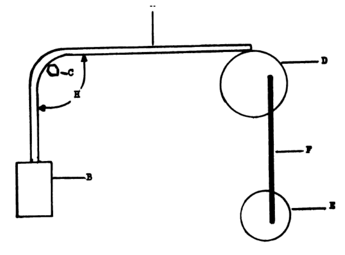
- Specimen
- Weight
- Steel hexagonal rods
- Drum
- Crank
- Crank arm
- 85-degree angle
Tag Cloud
- 7/16" Twist Shackle
- A-Frame
- Adjustable Anchor Webbing
- Aero 2
- Alpine WebLock 4.0
- Alpine WebLock 5.0
- Alpine WebLock 6.0
- Alpine WebLock 6.1
- Anchor Slings
- BC LineBag 2.0
- BC LineGrip G5
- BC Roller
- BC SS Shackle
- Blue
- Blue Spansets
- brake
- Buckingham System
- CMC MPD
- Drop Test
- Dyneema
- Edelrid Eddy
- Feather PRO
- Fiber-Reinforced Slackline Tape
- Gear Information
- Gear Storage
- Gear Test
- Gear Testing
- Gear Usage
- GGBY
- Green
- Green 20
- Guest Article
- Handled Ascender
- Hang Frame
- Highline Festival
- Highline Gear
- Highline Rigging
- Highline Safety
- Jelly PRO
- Lift
- Lift 2be
- Linebag
- LineGrip
- Longline Kit
- Longline Rigging
- Mantra MK4: Flight
- MightyLock
- Multiplier
- Paradigm
- Paradigm Signature
- Petzl Grigri
- Petzl I'D
- Petzl RIG
- Pharaoh
- Pulley System
- Pulleys
- Purchase Guide
- Rigging Plate
- Rock Exotica PentaPlate
- Rock Exotica Pulleys
- Rodeoline
- Safety
- SBI Pulley System
- Secondaire
- Shackle Line-Locker
- shackles
- Slackline Kit
- Slackline Webbing
- SMC 3-Inch Double PMP
- SMC 3-Inch Single PMP
- SMC CRx
- SMC Large Rigging Plate
- Soft Shackle
- Spansets
- Spider Silk MK4
- Static Rope
- Tape
- tensioning
- Testing Procedures
- Threaded Highline Leash
- Van Beest 1/2" Anchor Shackle
- Van Beest 5/8" Bolt-Type Shackle
- Velcro Line-Sleeve
- Wafer 2.0
- Wafer XL
- Walking Techniques
- Webbing Sleeve
- webbing tests
- Wind Dampener Kit

← Older Post Newer Post →
0 comments